Gas pipeline flow rate and velocity tables are important tools for measuring gas flow parameters in industrial production and laboratory research. They are widely used in fields such as chemical engineering, pharmaceuticals, energy, and environmental protection. This article will systematically introduce the basic concepts, common types, working principles, installation and usage methods, maintenance precautions, and solutions to common malfunctions of gas flow meters. It aims to help readers comprehensively master this technology and improve their practical application abilities.

I. Basic Concepts of Gas Pipeline Flow Rate and Velocity Tables
1.1 Definitions of Flow Rate and Velocity
Flow rate refers to the volume or mass of gas passing through a cross - section of a pipeline within a unit of time. Common units include m³/h (cubic meters per hour), L/min (liters per minute), or kg/h (kilograms per hour). Velocity, on the other hand, refers to the flow speed of gas in the pipeline, with the unit of m/s (meters per second).
There is the following mathematical relationship between flow rate and velocity:
Flow rate (Q) = Velocity (v) × Pipeline cross - sectional area (A)

1.2 Common Unit Conversions
In practical applications, different industries may adopt different unit systems. The common conversion relationships include:
- 1 m³/h≈16.67L/min
- 1 Nm³/h (normal cubic meters per hour)= the volume flow rate of gas under the conditions of 0℃ and 1 atmospheric pressure
- 1 SCFM (standard cubic feet per minute)≈1.699m³/h
II. Common Types of Gas Flow Meters and Their Working Principles
2.1 Differential Pressure Flow Meters
Differential pressure flow meters are based on the principle of Bernoulli's equation. They calculate the flow rate by measuring the pressure difference generated during the fluid flow. Common types include:

1. Orifice Plate Flowmeter: It calculates the flow rate by measuring the pressure difference generated before and after the gas flows through the orifice plate. It has a simple structure but causes relatively large pressure loss.
.gif")
2. Venturi tube: The cross-section changes from wide to narrow and then to wide again. The flow rate is calculated by measuring the pressure difference between the wide and narrow openings, and it has a relatively small pressure loss.
.gif")
3. Nozzle Flowmeter: It combines the characteristics of orifice plates and venturi tubes and is suitable for measuring high-speed gas flows.
.gif")
Advantages: Simple structure, high reliability, and adaptable to a wide range of flow velocity changes.
Disadvantages: Sensitive to pressure fluctuations, requires regular calibration, and is not suitable for low-pressure difference or corrosive gases.
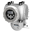
2.2 Thermal Mass Flow Meter
Thermal gas mass flow meters adopt the principle of thermal diffusion. The typical sensing elements include two resistance temperature detectors (RTDs): a velocity sensor and a temperature sensor.
Working Principle: The mass flow rate of the gas flowing through the sensor is calculated based on the amount of heat transfer. As the gas velocity increases, more heat will be carried away. To maintain a constant temperature, the operating current needs to be increased, and the increase is proportional to the flow velocity.
Advantages: Directly measures mass flow rate without the need for temperature and pressure compensation; has no moving parts, high reliability; fast response speed.
Disadvantages: Sensitive to installation direction; not suitable for gases containing liquid droplets or particles.
2.3 Vortex Flow Meter
Vortex flow meters are based on the Karman vortex street principle. A triangular prism-shaped vortex generator is set in the fluid, and regular vortices (Karman vortices) are alternately generated on both sides. The flow velocity is determined by detecting the vortex frequency.
.gif")
Technical parameters:
- Measured media: gases, liquids, vapors
- Normal measurement flow velocity range: 5 - 50 m/s for gases
- Reynolds number range: 1.5×10⁴ ~ 4×10⁶
Advantages: No moving parts, low maintenance requirements; wide application range; relatively high accuracy.
Disadvantages: Sensitive to pipeline vibration; measurement accuracy decreases at low flow velocities.
2.4 Turbine Flow Meter
It measures the flow velocity by measuring the rotational speed of the turbine in the fluid and is applicable to various liquid and gas media.
Advantages: Simple structure, relatively low cost, and wide application.
Disadvantages: Bearings are prone to wear and require regular maintenance; high requirements for fluid cleanliness.
2.5 Ultrasonic Flow Meter
It calculates the flow velocity by measuring the time difference between the ultrasonic waves propagating downstream and upstream in the gas flow.
Advantages: No pressure loss; can measure large - diameter pipelines; non - contact measurement.
Disadvantages: High price; strict requirements for installation location.
III. Installation and Usage Guide for Gas Flow Meters
3.1 Pre - installation Preparations
1. Flow meter selection: Select the appropriate type of flow meter according to the properties of the gas (temperature, pressure, composition, etc.).
2. Equipment inspection: Confirm that there is no damage to the appearance and that the calibration status is normal.
3. Pipeline preparation: Ensure that there are no welding slag, impurities, or other substances in the pipeline that may damage the flow meter.
.gif")
3.2 Selection of Installation Location
1. It should be installed on the straight section of the pipeline, avoiding installation near disturbance sources such as elbows and valves. Generally, the requirements are as follows:
- The length of the upstream straight pipe section ≥ 10 times the pipe diameter.
- The length of the downstream straight pipe section ≥ 5 times the pipe diameter.
2. Consider the convenience of maintenance and reserve sufficient operating space.
3. Determine the installation direction according to the type of flow meter:
- Thermal mass flow meters usually have requirements for the installation direction.
- Differential pressure flow meters need to pay attention to the direction of the pressure - taking port.
3.3 Installation Steps
1. Sealing treatment: Ensure that the connection between the flow meter and the pipeline is well - sealed to prevent leakage. Commonly used sealing materials include PTFE gaskets and graphite gaskets.
2. Electrical connection: Wire correctly according to the instruction manual, especially pay attention not to connect the signal wire and the power wire wrongly.
3. Grounding treatment: Some types of flow meters (such as electromagnetic ones) need to be well - grounded to eliminate interference.
4. Support and fixation: For large - diameter flow meters, additional support should be added to avoid the influence of pipeline stress on the measurement accuracy.
3.4 Pre - use Commissioning
1. Pre - heating: Electronic flow meters usually need to be pre - heated for 20 - 30 minutes to reach a stable state.
2. Zero - point calibration: Check and calibrate the zero - point under the non - flowing state.
3. Range setting: Set an appropriate range according to the actual operating conditions.
4. Parameter setting: Input parameters such as gas type, pipeline size, temperature, and pressure.
IV. Common Gas Pipeline Flow Rate and Velocity Comparison Tables
The following table lists the flow rate reference values of common pipe diameters under different flow velocities (calculated based on full - pipe flow in circular pipes):
工程通径 | 内径(mm) | 流速10m/s时流量(m³/h) | 流速15m/s时流量(m³/h) | 流速20m/s时流量(m³/h) |
DN15 | 15.8 | 7.05 | 10.58 | 14.10 |
DN20 | 21.3 | 12.82 | 19.23 | 25.64 |
DN25 | 27.0 | 20.60 | 30.90 | 41.20 |
DN32 | 35.8 | 36.22 | 54.33 | 72.44 |
DN40 | 41.0 | 47.51 | 71.27 | 95.03 |
DN50 | 53.0 | 79.38 | 119.07 | 158.76 |
DN65 | 68.0 | 130.67 | 196.01 | 261.34 |
DN80 | 80.5 | 183.13 | 274.70 | 366.26 |
DN100 | 106.0 | 317.53 | 476.30 | 635.06 |
DN125 | 131.0 | 484.97 | 727.46 | 969.94 |
DN150 | 156.0 | 687.74 | 1031.61 | 1375.48 |
DN200 | 200.0 | 1130.40 | 1695.60 | 2260.80 |
Note: The actual flow rate may vary due to factors such as gas properties, temperature, pressure, and pipeline roughness.
V. Maintenance and Troubleshooting of Gas Flow Meters
5.1 Routine Maintenance
1. Regular inspection: Conduct an appearance inspection at least once a month to confirm there is no leakage or corrosion.
2. Cleaning and maintenance: Clean the sensor part regularly according to the operating environment to prevent dust accumulation from affecting the measurement.
3. Calibration cycle: Generally, conduct professional calibration once every 12 months. Shorten the cycle under harsh conditions.
4. Battery replacement: Regularly check the battery status of portable flow meters or those with backup batteries.
5.2 Common Malfunctions and Solutions
1. Unstable readings:
- Possible causes: Pipeline vibration, air flow pulsation, electrical interference.
- Solutions: Add pipeline supports, install pulsation dampers, and check the grounding.
2. Zero - point drift:
- Possible causes: Sensor contamination, significant temperature changes.
- Solutions: Clean the sensor and recalibrate the zero - point.
3. No signal output:
- Possible causes: Power failure, incorrect wiring, blown fuse.
- Solutions: Check the power supply voltage, confirm the correct wiring, and replace the fuse.
4. Large deviation in measured values:
- Possible causes: Incorrect parameter settings, sensor damage, change in medium.
- Solutions: Re - set the parameters, check the sensor status, and confirm whether the properties of the medium have changed.
Conclusion
Gas pipeline flow rate and velocity tables are indispensable tools in industrial measurement. Correct selection, installation, and maintenance are crucial for ensuring measurement accuracy and equipment lifespan. It is hoped that through the systematic introduction of this article, readers can better understand and apply gas flow meter technology, improving work efficiency and system reliability.


 Consultation Tel.
 Product Center
 Solution
 Home
Home